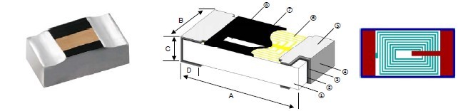
| Thin Film Chip Inductor��AL Series |
|
 |
| |
1 |
Alumina Substrate |
4 |
External Electrode (Sn) |
7 |
Overcoat |
2 |
Inner Electrode (Ni-Cr) |
5 |
Edge Electrode |
8 |
Marking |
3 |
Barrier Layer (Ni) |
6 |
Cu Circuits |
|
|
|
| |
| ��Features |
��Dimensions |
Unit: mm |
|
��Photolithographic single layer ceramic chip
��High SRF, excellent Q, superior temperature stability
��Tight tolerance of �� 1% or �� 0.1nH
��Self resonant frequency controlled within 10%
��Stable inductance in high frequency circuit
��Highly stable design for critical needs |
Type |
Size
(Inch) |
A |
B |
C |
D |
Weight
(g)
(1000pcs) |
AL01 |
0201 |
0.60��0.05 |
0.30��0.05 |
0.23��0.05 |
0.15��0.05 |
0.3 |
AL02 |
0402 |
1.0��0.05 |
0.5��0.05 |
0.32��0.05 |
0.2��0.10 |
0.9 |
AL03 |
0603 |
1.6��0.10 |
0.8��0.10 |
0.45��0.10 |
0.3��0.20 |
2.97 |
|
|
| |
��Applications
��Cellular Telephone, Pagers and GPS Products
��VCO, TCXO Circuit and RF Transceiver Module
��Wireless LAN, Bluetooth Module, Communication
Appliances |
| |
��Part Numbering |
|
|
|
|
|
|
|
|
|
|
|
Dimensions |
01: 0201
02: 0402
03: 0603 |
|
Inductance
Tolerance |
B: ��0.1nH
C: ��0.2nH
S: ��0.3nH
W: ��0.05nH
F: ��1%
G: ��2%
H: ��3%
J: ��5% |
|
Packaging
Code |
| T: Taping Reel |
|
Inductance |
1N0: 1nH
10N: 10nH
20N8: 20.8nH
R10: 100nH |
|
| |
|
|
|
|
| |
|
|
|
|
|
|
Viking is capable of manufacturing the optional spec based on customer��s requirement. |
| |
| |
��Standard Electrical Specifications |
AL01 Chip Inductors / Standard Type |
Inductance
(nH) |
Inductance
Tolerance
(nH or %) |
Quality Factor
min. |
SRF
(GHz) min. |
DCR
(��) max. |
IDC
(mA) max. |
0.1 |
��0.1, 0.2, 0.3nH |
8 / 500MHz |
9 |
0.20 |
400 |
0.2 |
��0.1, 0.2, 0.3nH |
8 / 500MHz |
9 |
0.20 |
400 |
0.3 |
��0.1, 0.2, 0.3nH |
8 / 500MHz |
9 |
0.20 |
400 |
0.4 |
��0.1, 0.2, 0.3nH |
8 / 500MHz |
9 |
0.25 |
350 |
0.5 |
��0.1, 0.2, 0.3nH |
8 / 500MHz |
9 |
0.25 |
350 |
0.6 |
��0.1, 0.2, 0.3nH |
8 / 500MHz |
9 |
0.25 |
350 |
0.7 |
��0.1, 0.2, 0.3nH |
8 / 500MHz |
9 |
0.30 |
300 |
0.8 |
��0.1, 0.2, 0.3nH |
8 / 500MHz |
9 |
0.30 |
300 |
0.9 |
��0.1, 0.2, 0.3nH |
8 / 500MHz |
9 |
0.30 |
300 |
1.0 |
��0.1, 0.2, 0.3nH |
8 / 500MHz |
9 |
0.30 |
300 |
1.1 |
��0.1, 0.2, 0.3nH |
8 / 500MHz |
9 |
0.35 |
300 |
1.2 |
��0.1, 0.2, 0.3nH |
8 / 500MHz |
9 |
0.35 |
300 |
1.3 |
��0.1, 0.2, 0.3nH |
8 / 500MHz |
9 |
0.45 |
250 |
1.4 |
��0.1, 0.2, 0.3nH |
8 / 500MHz |
9 |
0.45 |
250 |
1.5 |
��0.1, 0.2, 0.3nH |
8 / 500MHz |
9 |
0.45 |
250 |
1.6 |
��0.1, 0.2, 0.3nH |
8 / 500MHz |
9 |
0.55 |
200 |
1.7 |
��0.1, 0.2, 0.3nH |
8 / 500MHz |
9 |
0.55 |
200 |
1.8 |
��0.1, 0.2, 0.3nH |
8 / 500MHz |
9 |
0.55 |
200 |
1.9 |
��0.1, 0.2, 0.3nH |
8 / 500MHz |
9 |
0.55 |
200 |
2.0 |
��0.1, 0.2, 0.3nH |
8 / 500MHz |
8 |
0.70 |
200 |
2.1 |
��0.1, 0.2, 0.3nH |
8 / 500MHz |
8 |
0.70 |
200 |
2.2 |
��0.1, 0.2, 0.3nH |
8 / 500MHz |
8 |
0.70 |
200 |
2.3 |
��0.1, 0.2, 0.3nH |
8 / 500MHz |
8 |
0.80 |
150 |
2.4 |
��0.1, 0.2, 0.3nH |
8 / 500MHz |
8 |
0.80 |
150 |
2.5 |
��0.1, 0.2, 0.3nH |
8 / 500MHz |
8 |
0.80 |
150 |
2.6 |
��0.1, 0.2, 0.3nH |
8 / 500MHz |
8 |
0.80 |
150 |
2.7 |
��0.1, 0.2, 0.3nH |
8 / 500MHz |
8 |
0.80 |
150 |
2.8 |
��0.1, 0.2, 0.3nH |
8 / 500MHz |
6 |
1.00 |
150 |
2.9 |
��0.1, 0.2, 0.3nH |
8 / 500MHz |
6 |
1.00 |
150 |
3.0 |
��0.1, 0.2, 0.3nH |
8 / 500MHz |
6 |
1.00 |
150 |
3.1 |
��0.1, 0.2, 0.3nH |
8 / 500MHz |
6 |
1.00 |
150 |
3.2 |
��0.1, 0.2, 0.3nH |
8 / 500MHz |
6 |
1.00 |
150 |
3.3 |
��0.1, 0.2, 0.3nH |
8 / 500MHz |
6 |
1.00 |
150 |
3.4 |
��0.1, 0.2, 0.3nH |
8 / 500MHz |
6 |
1.20 |
150 |
3.5 |
��0.1, 0.2, 0.3nH |
8 / 500MHz |
6 |
1.20 |
150 |
3.6 |
��0.1, 0.2, 0.3nH |
8 / 500MHz |
6 |
1.20 |
150 |
3.7 |
��0.1, 0.2, 0.3nH |
8 / 500MHz |
6 |
1.20 |
150 |
3.8 |
��0.1, 0.2, 0.3nH |
8 / 500MHz |
6 |
1.20 |
150 |
3.9 |
��0.1, 0.2, 0.3nH |
8 / 500MHz |
6 |
1.20 |
150 |
4.0 |
��0.1, 0.2, 0.3nH |
8 / 500MHz |
6 |
1.20 |
150 |
4.4 |
��0.1, 0.2, 0.3nH |
8 / 500MHz |
6 |
1.30 |
140 |
4.7 |
��0.1, 0.2, 0.3nH |
8 / 500MHz |
6 |
1.40 |
130 |
4.9 |
��0.1, 0.2, 0.3nH |
8 / 500MHz |
6 |
1.60 |
130 |
5.6 |
��2, ��5% |
8 / 500MHz |
4 |
1.80 |
130 |
6.1 |
��2, ��5% |
8 / 500MHz |
4 |
2.00 |
120 |
6.8 |
��2, ��5% |
8 / 500MHz |
4 |
2.30 |
110 |
7.4 |
��2, ��5% |
8 / 500MHz |
4 |
2.80 |
110 |
8.2 |
��2, ��5% |
8 / 500MHz |
3 |
3.00 |
110 |
9.1 |
��2, ��5% |
8 / 500MHz |
3 |
3.25 |
100 |
9.2 |
��2, ��5% |
8 / 500MHz |
3 |
3.25 |
100 |
10 |
��2, ��5% |
8 / 500MHz |
2 |
3.50 |
80 |
|
| |
| |
AL02 Chip Inductors / Standard Type |
Inductance
(nH) |
Inductance
Tolerance
(nH or %) |
Quality Factor
min. |
SRF
(GHz) min. |
DCR
(��) max. |
IDC
(mA) max. |
0.2 |
��0.1, 0.2, 0.3nH |
13 / 500MHz |
14 |
0.10 |
800 |
0.3 |
��0.1, 0.2, 0.3nH |
13 / 500MHz |
14 |
0.10 |
800 |
0.4 |
��0.1, 0.2, 0.3nH |
13 / 500MHz |
14 |
0.10 |
800 |
0.5 |
��0.1, 0.2, 0.3nH |
13 / 500MHz |
14 |
0.15 |
700 |
0.8 |
��0.1, 0.2, 0.3nH |
13 / 500MHz |
14 |
0.15 |
700 |
0.9 |
��0.1, 0.2, 0.3nH |
13 / 500MHz |
14 |
0.15 |
700 |
1.0 |
��0.1, 0.2, 0.3nH |
13 / 500MHz |
12 |
0.15 |
700 |
1.1 |
��0.1, 0.2, 0.3nH |
13 / 500MHz |
12 |
0.15 |
700 |
1.2 |
��0.1, 0.2, 0.3nH |
13 / 500MHz |
12 |
0.15 |
700 |
1.3 |
��0.1, 0.2, 0.3nH |
13 / 500MHz |
10 |
0.25 |
700 |
1.4 |
��0.1, 0.2, 0.3nH |
13 / 500MHz |
10 |
0.25 |
700 |
1.5 |
��0.1, 0.2, 0.3nH |
13 / 500MHz |
10 |
0.25 |
700 |
1.6 |
��0.1, 0.2, 0.3nH |
13 / 500MHz |
10 |
0.25 |
560 |
1.7 |
��0.1, 0.2, 0.3nH |
13 / 500MHz |
10 |
0.25 |
560 |
1.8 |
��0.1, 0.2, 0.3nH |
13 / 500MHz |
10 |
0.25 |
560 |
1.9 |
��0.1, 0.2, 0.3nH |
13 / 500MHz |
8 |
0.35 |
560 |
2.0 |
��0.1, 0.2, 0.3nH |
13 / 500MHz |
8 |
0.35 |
560 |
2.1 |
��0.1, 0.2, 0.3nH |
13 / 500MHz |
8 |
0.35 |
440 |
2.2 |
��0.1, 0.2, 0.3nH |
13 / 500MHz |
8 |
0.35 |
440 |
2.3 |
��0.1, 0.2, 0.3nH |
13 / 500MHz |
8 |
0.35 |
440 |
2.4 |
��0.1, 0.2, 0.3nH |
13 / 500MHz |
8 |
0.35 |
440 |
2.5 |
��0.1, 0.2, 0.3nH |
13 / 500MHz |
8 |
0.35 |
440 |
2.6 |
��0.1, 0.2, 0.3nH |
13 / 500MHz |
8 |
0.35 |
440 |
2.7 |
��0.1, 0.2, 0.3nH |
13 / 500MHz |
8 |
0.35 |
440 |
2.8 |
��0.1, 0.2, 0.3nH |
13 / 500MHz |
6 |
0.45 |
380 |
2.9 |
��0.1, 0.2, 0.3nH |
13 / 500MHz |
6 |
0.45 |
380 |
3.0 |
��0.1, 0.2, 0.3nH |
13 / 500MHz |
6 |
0.45 |
380 |
3.1 |
��0.1, 0.2, 0.3nH |
13 / 500MHz |
6 |
0.45 |
380 |
3.2 |
��0.1, 0.2, 0.3nH |
13 / 500MHz |
6 |
0.45 |
380 |
3.3 |
��0.1, 0.2, 0.3nH |
13 / 500MHz |
6 |
0.45 |
380 |
3.4 |
��0.1, 0.2, 0.3nH |
13 / 500MHz |
6 |
0.55 |
380 |
3.5 |
��0.1, 0.2, 0.3nH |
13 / 500MHz |
6 |
0.55 |
380 |
3.6 |
��0.1, 0.2, 0.3nH |
13 / 500MHz |
6 |
0.55 |
380 |
3.7 |
��0.1, 0.2, 0.3nH |
13 / 500MHz |
6 |
0.55 |
340 |
3.8 |
��0.1, 0.2, 0.3nH |
13 / 500MHz |
6 |
0.55 |
340 |
3.9 |
��0.1, 0.2, 0.3nH |
13 / 500MHz |
6 |
0.55 |
340 |
4.3 |
��0.1, 0.2, 0.3nH |
13 / 500MHz |
6 |
0.65 |
320 |
4.7 |
��0.1, 0.2, 0.3nH |
13 / 500MHz |
6 |
0.65 |
320 |
5.4 |
��0.1, 0.2, 0.3nH |
13 / 500MHz |
6 |
0.85 |
280 |
5.6 |
��0.1, 0.2, 0.3nH |
13 / 500MHz |
6 |
0.85 |
280 |
5.9 |
��0.1, 0.2, 0.3nH |
13 / 500MHz |
6 |
0.85 |
280 |
6.5 |
��0.1, 0.2, 0.3nH |
13 / 500MHz |
6 |
1.05 |
260 |
6.8 |
��0.1, 0.2, 0.3nH |
13 / 500MHz |
6 |
1.05 |
260 |
7.2 |
��0.1, 0.2, 0.3nH |
13 / 500MHz |
6 |
1.05 |
260 |
8.0 |
��0.1, 0.2, 0.3nH |
13 / 500MHz |
5.5 |
1.25 |
220 |
8.1 |
��0.1, 0.2, 0.3nH |
13 / 500MHz |
5.5 |
1.25 |
220 |
8.2 |
��0.1, 0.2, 0.3nH |
13 / 500MHz |
5.5 |
1.25 |
220 |
9.1 |
��0.1, 0.2, 0.3nH |
13 / 500MHz |
5.5 |
1.25 |
220 |
10.0 |
��1, 2, 3, 5% |
13 / 500MHz |
4.5 |
1.35 |
200 |
10.8 |
��1, 2, 3, 5% |
13 / 500MHz |
4.5 |
1.35 |
200 |
12.0 |
��1, 2, 3, 5% |
13 / 500MHz |
3.7 |
1.55 |
180 |
13.8 |
��1, 2, 3, 5% |
13 / 500MHz |
3.7 |
1.75 |
180 |
15.0 |
��1, 2, 3, 5% |
13 / 500MHz |
3.3 |
1.75 |
130 |
17.0 |
��1, 2, 3, 5% |
13 / 500MHz |
3.1 |
1.95 |
100 |
18.0 |
��1, 2, 3, 5% |
13 / 500MHz |
3.1 |
2.15 |
100 |
20.8 |
��1, 2, 3, 5% |
13 / 500MHz |
2.8 |
2.55 |
90 |
22.0 |
��1, 2, 3, 5% |
13 / 500MHz |
2.8 |
2.65 |
90 |
27.0 |
��1, 2, 3, 5% |
13 / 500MHz |
2.5 |
3.25 |
75 |
33.0 |
��5% |
13 / 500MHz |
2.5 |
4.50 |
75 |
|
| |
| |
AL03 Chip Inductors / Standard Type |
Inductance
(nH) |
Inductance
Tolerance
(nH or %) |
Quality Factor
min. |
SRF
(GHz) min. |
DCR
(��) max. |
IDC
(mA) max. |
1.0 |
��0.1,0.2,0.3nH |
15/300MHz |
13 |
0.35 |
800 |
1.2 |
��0.1,0.2,0.3nH |
15/300MHz |
13 |
0.35 |
800 |
1.5 |
��0.1,0.2,0.3nH |
15/300MHz |
10 |
0.35 |
800 |
1.8 |
��0.1,0.2,0.3nH |
15/300MHz |
10 |
0.35 |
300 |
2.2 |
��0.1,0.2,0.3nH |
15/300MHz |
8 |
0.35 |
300 |
2.7 |
��0.1,0.2,0.3nH |
15/300MHz |
6 |
0.45 |
300 |
3.3 |
��0.1,0.2,0.3nH |
15/300MHz |
6 |
0.45 |
300 |
3.9 |
��0.1,0.2,0.3nH |
15/300MHz |
6 |
0.45 |
300 |
4.7 |
��0.1,0.2,0.3nH |
15/300MHz |
5 |
0.55 |
300 |
5.6 |
��0.1,0.2,0.3nH |
15/300MHz |
5 |
0.65 |
300 |
6.8 |
��0.1,0.2,0.3nH |
15/300MHz |
5 |
0.75 |
300 |
8.2 |
��0.1,0.2,0.3nH |
15/300MHz |
4 |
0.95 |
300 |
10 |
��1,2,3,5% |
15/300MHz |
4 |
0.95 |
300 |
12 |
��1,2,3,5% |
15/300MHz |
3 |
1.05 |
300 |
15 |
��1,2,3,5% |
15/300MHz |
3 |
1.35 |
300 |
18 |
��1,2,3,5% |
15/300MHz |
2 |
1.65 |
300 |
22 |
��1,2,3,5% |
15/300MHz |
2 |
1.95 |
250 |
27 |
��1,2,3,5% |
15/300MHz |
2 |
2.35 |
250 |
33 |
��1,2,3,5% |
15/300MHz |
1.5 |
2.75 |
250 |
39 |
��1,2,3,5% |
15/300MHz |
1.5 |
3.00 |
200 |
47 |
��1,2,3,5% |
15/300MHz |
1.5 |
3.00 |
200 |
56 |
��1,2,3,5% |
15/300MHz |
1 |
5.00 |
150 |
68 |
��1,2,3,5% |
15/300MHz |
1 |
5.00 |
150 |
100 |
��2,3,5% |
15/300MHz |
1 |
7.50 |
100 |
|
| |
��Environmental Characteristics |
Item |
Requirement |
Test Method |
| Inductance |
As Spec. |
Measuring equipment and fixture:
0201: HP4287+Agilent 16196C
0402: HP4287+Agilent 16196B
0603: HP4287+Agilent 16196A |
| Insulation Resistance |
>1000M�� |
Apply 100VDC for 1minute |
| Damp Heat with Load |
��L�Q10% |
40��2��C, 90~95% R.H. Max. working voltage for 1000 hrs with 1.5 hrs
��ON�� and 0.5 hrs ��OFF�� |
| Bending Strength |
As Spec. |
Bending Amplitude 3mm for 10 seconds |
| Solderability |
95% min. coverage |
245��5��C for 3 seconds |
| Resistance to Soldering Heat |
��L�Q10% |
260��5��C for 10 seconds |
| Dielectric Withstand Voltage |
>100V |
Apply 100VA (rms) for 1minute |
| High Temperature Exposure |
��L�Q10% |
85��2��C, 1000 +48/-0 hours |
| Low Temperature Storage |
��L�Q10% |
-40��3��C, 1000 +48/-0 hours |
| Temperature Cycle |
��L�Q10% |
-40/RT/85/RT, 10 cycles |
|
��Reference Standards: MIL-STD-202F, JIS-C 5201-1 |
��Storage Temperature: 25��3��C; Humidity < 80%RH |
| |
��Packaging |
| |
| |
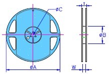
Reel Specifications & Packaging Quantity |
Unit: mm |
|
|
Type |
��A |
��B |
��C |
W |
T |
Quantity
(EA) |
| AL01 |
178.0��1.0 |
60+1.0 |
13.5��0.7 |
9.5��1.0 |
11.5��1.0 |
10,000 |
| AL02 |
178.0��1.0 |
60+1.0 |
13.5��0.7 |
9.5��1.0 |
11.5��1.0 |
10,000 |
| AL03 |
178.0��1.0 |
60+1.0 |
13.5��0.7 |
9.5��1.0 |
11.5��1.0 |
5,000 |
|
|
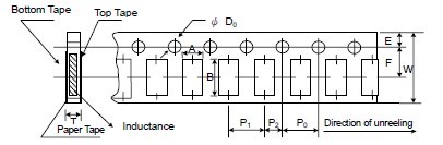
Paper Tape Specifications |
|
| |
|
| |
Unit: mm |
| Type |
A |
B |
W |
E |
F |
P0 |
P1 |
P2 |
��D0 |
T |
| AL01 |
0.40��0.05 |
0.70��0.05 |
8.00��0.10 |
1.75��0.05 |
3.5��0.05 |
4.00��0.10 |
2.00��0.05 |
2.00��0.05 |
1.55��0.03 |
0.42��0.02 |
| AL02 |
0.70��0.05 |
1.16��0.05 |
8.00��0.10 |
1.75��0.05 |
3.5��0.05 |
4.00��0.10 |
2.00��0.05 |
2.00��0.05 |
1.55��0.03 |
0.40��0.03 |
| AL03 |
1.10��0.05 |
1.90��0.05 |
8.00��0.10 |
1.75��0.05 |
3.5��0.05 |
4.00��0.10 |
4.00��0.10 |
2.00��0.05 |
1.55��0.03 |
0.60��0.03 |
|
| |
|