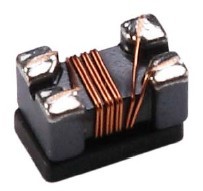
| Chip Common Mode Filter��CM Series |
|
 |
 |
| �� |
Terminal |
�� |
Ferrite |
�� |
Enamel-insulated Wire |
|
|
|
| ��Features |
��Small chip inductor with ferrite core and two line types
wire wound
��Highly effective in noise suppression High
common-mode impedance at noise band and low
differential-mode impedance at signal band
��Low differential-mode impedance with high coupling
factor. There is almost no distortion on high-speed
signal.
��Operating temperature -40��C~85��C |
|
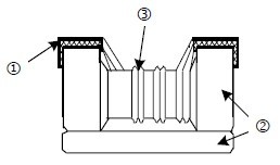
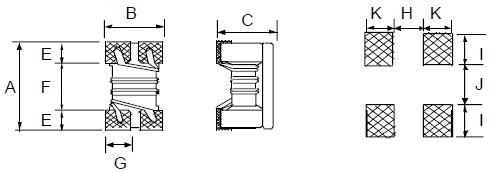
| ��Dimensions |
 |
|
|
| ��Applications |
��EMI Radiation Noise Suppression for Any Electronic
Device
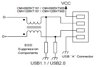
��USB Line for Personal Computers and Peripheral
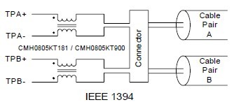
��IEEE 1394 Line for Personal Computers, DVC, STB
��LCD Panels. Low-Voltage Differential Signal (LVDS) |
|
Unit: mm |
| Type |
Size
(Inch) |
A |
B |
C |
E |
F |
G |
H |
I |
J |
K |
Weight
(g)
(1000pcs) |
| CMH05 |
0805 |
2.0��0.2 |
1.2��0.2 |
1.2��0.2 |
0.45 |
1.2 |
0.4 |
0.8 |
0.4 |
0.4 |
0.90 |
19 |
| CMH06 |
1206 |
3.2��0.2 |
1.6��0.2 |
1.8��0.2 |
0.60 |
2.0 |
0.6 |
1.6 |
0.6 |
0.4 |
1.05 |
53.3 |
|
|
|
|
| ��Part Numbering |
|
|
|
|
|
|
|
|
|
|
|
 |
|
|
|
|
|
|
|
|
|
|
|
|
Shielding
Type |
H: Shielding |
|
|
| Dimensions |
05: 0805
06: 1206 |
|
|
Impedance
Tolerance |
M: ��20% |
|
|
Packaging
Code |
T: Taping Reel
B: Bulk |
|
|
| Impedance |
900: 90��
121: 120��
102: 1000��
222: 2200�� |
|
|
|
| ��Standard Electrical Specifications |
|
|
Impedance
(��) |
Tolerance |
Test
Condition
(MHz) |
DCR
(��) max. |
IDC
(mA) max. |
Rated Voltage
Vdc (V) |
Withstanding
Voltage Vdc
(V |
Insulation
Resistance
(M��) min. |
| 67 |
��20% |
100 |
0.25 |
400 |
50 |
125 |
10 |
| 90 |
��20% |
100 |
0.35 |
330 |
50 |
125 |
10 |
| 120 |
��20% |
100 |
0.30 |
370 |
50 |
125 |
10 |
| 180 |
��20% |
100 |
0.35 |
330 |
50 |
125 |
10 |
| 200 |
��20% |
100 |
0.35 |
330 |
50 |
125 |
10 |
| 260 |
��20% |
100 |
0.40 |
300 |
50 |
125 |
10 |
| 360 |
��20% |
100 |
0.40 |
280 |
50 |
125 |
10 |
| 370 |
��20% |
100 |
0.40 |
280 |
50 |
125 |
10 |
|
|
|
Impedance
(��) |
Tolerance |
Test
Condition
(MHz) |
DCR
(��) max. |
IDC
(mA) max. |
Rated Voltage
Vdc (V) |
Withstanding
Voltage Vdc
(V) |
Insulation
Resistance
(M��) min. |
| 90 |
��20% |
100 |
0.30 |
370 |
50 |
125 |
10 |
| 160 |
��20% |
100 |
0.40 |
340 |
50 |
125 |
10 |
| 260 |
��20% |
100 |
0.50 |
310 |
50 |
125 |
10 |
| 600 |
��20% |
100 |
0.80 |
260 |
50 |
125 |
10 |
| 1000 |
��20% |
100 |
1.00 |
230 |
50 |
125 |
10 |
| 2200 |
��20% |
100 |
1.20 |
200 |
50 |
125 |
10 |
|
|
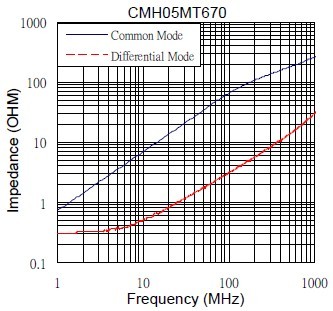
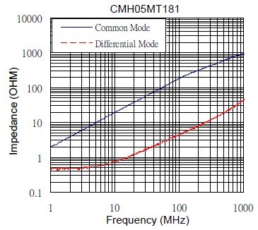
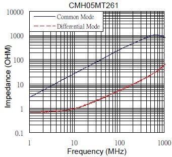
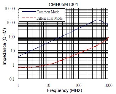
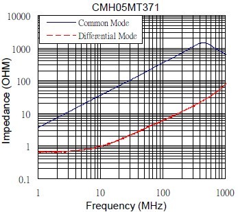
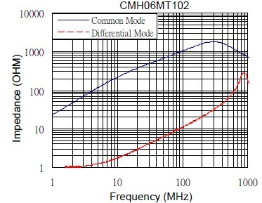
| ��Characteristics (Impedance vs. Frequency)-CMH05 |
|
|
|
|
|
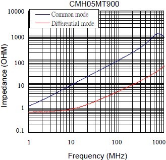
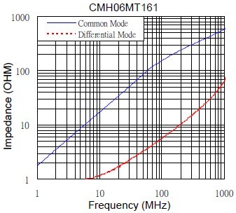
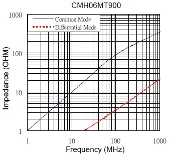
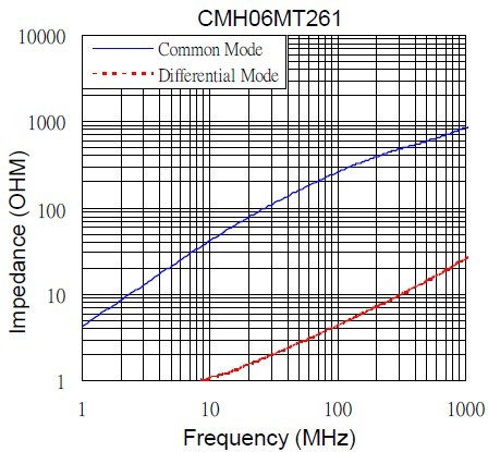
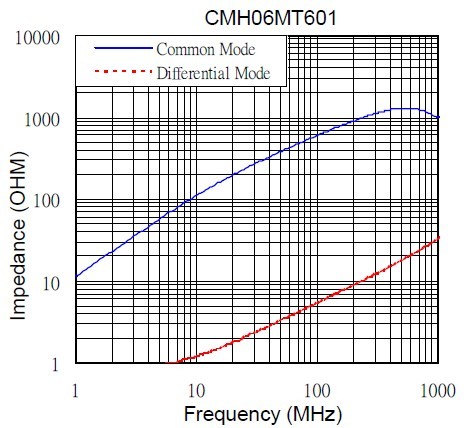
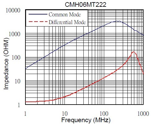
| ��Characteristics (Impedance vs. Frequency)-C06 |
|
|
|
|
| ��Environmental Characteristics |
|
| Electrical Performance Test |
| Items |
Requirement |
Test Conditions / Test Methods |
| Impedance |
Refer to standard electrical
characteristic spec.
Component should not be damaged |
LCR Meter HP 4291B |
| DC Resistance DCR |
Micro-Ohm meter (GOM-801G) |
Withstand Voltage (VDC)
Rated Voltage (VDC) |
Test Voltage: 2.5 Times Rated Voltage
Testing Time: 60 seconds
Charge Current: 0.5mA
Test Voltage: Rated Voltage
Testing Time: 1 to 5 seconds
Charge Current: 1mA |
| Insulation Resistance (I.R) |
Charge Current: 1minute
10M ohm min. |
|
| Mechanical Performance Test |
| Items |
Requirement |
Test Conditions / Test Methods |
Component Adhesion
(Push Test) |
Base: 0805�R2 Lbs
Cover: 0805�R1 Lbs
Base: 1206�R4 Lbs
Cover: 1206�R2 Lbs |
The component should be soldered (232��C �� 5��C for 10 sec.) to
tinned copper substrate
Applied force gauge to the side of component It must withstand
force of 2 or 4 pounds without failure of the component. |
Drop
Solderability |
Component should not be damaged
The terminal should at least be 90%
covered with solder |
Dropping chip by each side and corner. Drop 10 times in total
Drop height: 100 cm
Drop weight: 125 g
The component shall be dipped in a melted solder bath at 245
��5��C for 3 seconds |
Vibration Test (Low Frequency) |
Component should not be damaged |
1. Amplitude: 1.5 m/m
2. Frequency: 10-55-10Hz (1min.)
3. Direction: X, Y, Z
4. Duration: 2 Hrs/X, Y, Z |
|
| Climatic Test |
| Items |
Requirement |
Test Conditions / Test Methods |
| Low Temperature Storage |
Impedance change: Within�� 20%
Without distinct damage in appearance
There should be no evidence of short or
open circuit
|
1. Temp: -40 ��2��C
2. Time: 1000��48 Hours
3. Component should be tested after 1hour at room temperature |
| Thermal Shock |
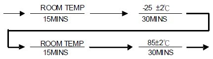
Total: 5 Cycles |
High Temperature Storage |
1. Temp: 85 �� 2��C
2. Time: 1000 �� 48 Hours
3. Component should be tested after 1hour at room temperature |
Humidity
High Temperature Load Life
Low Temperature Load Life |
1. Temp: 40 �� 2��C
2. R.H. : 90 ~ 95%
3. Time: 48 ��2 Hours
1. Temp: 85 �� 2��C
2. Time: 96 �� 12 Hours
3. Load: Allowed DC Current
1. Temp: -40 �� 2��C
2. Time: 96 �� 12 Hours
3. Load: Allowed DC Current |
|
| |
|
|
| ��Storage Temperature: 25��3��C; Humidity < 80%RH |
|
|
|
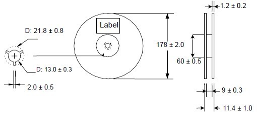
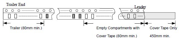
| Packaging Quantity |
Reel Specifications |
| Type |
EmbossedPlastic Tape(EA) |
| CMH05 |
2,000 |
| CMH06 |
2,000 |
|
 |
|
| Embossed Plastic Tape Specifications |
|
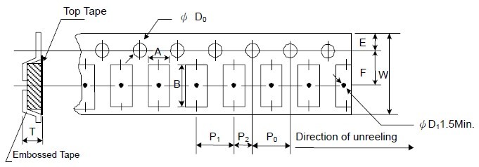 |
| Unit: mm |
| Type |
A |
B |
W |
E |
F |
P0 |
P1 |
P2 |
��D0 |
T |
| CMH05 |
1.40��0.10 |
2.55��0.05 |
8.0��0.20 |
1.75��0.10 |
3.5��0.10 |
4.00��0.10 |
4.00��0.10 |
2.00��0.10 |
1.50+0.10 |
1.35��0.10 |
| CMH06 |
1.90��0.10 |
3.50��0.05 |
8.0��0.20 |
1.75��0.10 |
3.5��0.10 |
4.00��0.10 |
4.00��0.10 |
2.00��0.10 |
1.50+0.10 |
2.10��0.10 |
|
|
|
 |
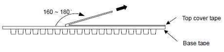
Peel-off Force
The force for tearing off cover tape is 0.05~0.69 (N) in the arrow direction at the following conditions:
Temperature: 5 ~ 35��C
Humidity: 45 ~ 85%
Atmospheric pressure: 860 ~ 1060hpa |
 |
| |